Single Drive Description
 In-Depth Description of Single Drive Wheels
Compared to the double drive set-up for spinning wheels,the single drive mechanics are rather new. The introduction of single drive wheels might have come about for the ease of fabricating the parts.
Single drive mechanics can be of two types: flyer lead or bobbin lead. The difference has to do with what the drive band is driving. In this section we will talk about the flyer lead system which is what the Kromski single drive wheels and most other manufacturers use.
With single drive wheels, there is a braking system typically referred to as Scotch tension. So as we talk about single drive here, we are referring to “single drive with Scotch tension braking.”
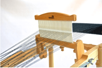
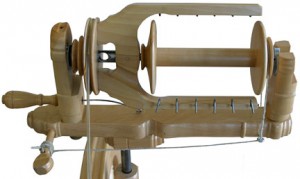
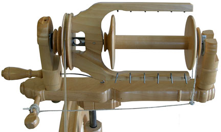
In a single drive set-up, the drive band loops around the drive wheel once and at the flyer it goes around “whorls” or pulleys built into the flyer unit, or in the case of the Kromski Fantasia, a separate whorl not connected to the flyer but rather “locked” to the spindle. The pulleys on the flyer (or Fantasia whorl) are different sizes; it is these different sizes that allow the spinner to control the speed or ratios of the wheel. Smaller pulleys cause the flyer to rotate faster and the larger pulleys will make the flyer turn slower. Slower or faster is also affected by how fast the spinner treadles, so speed is a two-part equation. Rotation speed at the flyer governs how quickly twist is imparted in the fibers being spun.
In addition to the drive band set-up, there is a braking system that is a critical component, without which take up of yarn can not take place. A brake band is normally a piece of string that loops over the pulley built into the bobbin. The tension on the brake band can be adjusted with the use of a spring on one end of the band and an adjusting peg on the other. The brake band is designed to create drag on the rotation of the bobbin, stopping its ability to rotate.
Here, in a list format, is what happens when a single drive drive wheel is set up properly:
Foot or feet actuate the treadle(s);
Treadle movement causes footman to rise and fall;
Footman pulls/pushes the crank on the drive wheel axle causing the wheel to rotate;
The drive wheel rotation will cause the drive band, if tensioned properly, to travel around the circumference of the wheel;
The moving drive band will cause the flyer mechanism to rotate if properly tensioned;
When yarn is secured to the bobbin core and routed through the flyer orifice and held securely in a spinner’s hands, the flyer and the bobbin will rotate in sync, locked together by the yarn between bobbin and flyer; the brake band on the bobbin pulley is actually slipping to allow this to happen;
When the spinner allows twisted yarn to advance into the orifice, a degree of tension is released on the yarn allowing the lock of the bobbin and flyer to fail; the rotation of the bobbin will begin to slow as the brake band tension reduces bobbin speed; because the bobbin and flyer are now rotating at different speeds, the yarn is pulled from the spinner’s hands and is wrapped on the bobbin.
With a single drive wheel, the spinner has two separate adjustments that can be made. First, the tension of the drive band from wheel to flyer – this tension should be just enough, and no more, to cause the flyer to rotate without slipping when the wheel begins to rotate. Inappropriate drive band tension is detrimental to the feel of treadling and is to be avoided. Second, the tension of the brake band on the bobbin pulley must be adjusted to set how aggressively the take-up of yarn onto the bobbin feels in the spinner’s hand.
Here are some other important aspects of the single drive design.
The rotation speed of the flyer can be adjusted by placing the drive band on a different diameter whorl groove or by treadle cadence, or both.
Since the drive band only impacts the positive rotation of the flyer, slipping is not a factor. This mean that the use of an elastic drive band that grips the flyer pulleys aggressively is a good thing as it allows the tension to be minimal which in turn improves the “feel” at the treadle.
The material used for the brake band is not terribly important provided it allows for slippage.
Tension on the brake band is affected by the diameter of the bobbin pulley, the thickness of the brake band, the composition of the brake band and the tension you apply to the brake band and spring. Generally speaking, not much tension is needed to retard the bobbin during take-up of yarn.
Single Drive Brack Tip for spinning and plying