Double Drive Description
 In-Depth Description of Double Drive Wheels
There was a time when spinning wheels did not have bobbins and flyers. Yarn was spun on a wheel that had just a spindle. While great yarn can be made in this manner, it was a slow process. Spinners had to do a long type of draw with the wheel rotating one direction, then wind the yarn on the spindle by reversing the wheel direction. Start. Stop. Start. Stop. A better idea was waiting to be discovered.
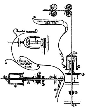
Leonardo da Vinci gave some thought to the efficiency of spinning, and it may have only taken a short time for him to visualize a mechanical method for allowing a continuous process of spinning yarn without stopping and allow the ability to store the yarn as production continued. It was all in his mind; however, he never actually made the devise. Rather, he drew a remarkable sketch which fortunately survived him. The production of the first double drive flyer can be attributed to Johann Jurgen of Germany.
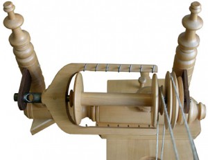
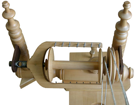
 There is virtually no difference in the basic design of this flyer from one wheel maker to the next. In most common practice, a single drive band long enough to loop around the various mechanical parts twice is the drive transmission device. Think of it doing the same thing that the drive belt on a car motor does. Using the energy source of a leg or two, the drive wheel is made to rotate. The speed of this rotation will impact the driven parts on the mother-of-all. The faster one treadles and the diameter of the drive wheel is one way to control the speed of the driven parts of the spinning wheel, the flyer and bobbin. The drive band is the intermediate part that transfers power from the drive wheel to the flyer.
But what happens at the flyer? How does the rotation of the flyer and bobbin result in the fibers turning into yarn and being drawn onto the bobbin?
The critical ingredients to this process are the diameter of the whorl (a pulley) and the pulley on the end of the bobbin, coupled with the design/shape of the grooves on the whorl and bobbin pulley.
The groove(s) on the whorl have a very distinct “V” shape to them, allowing the drive band to sit at the very bottom and grip the sides of the groove. This gripping is what allows the flyer to be rotated as the drive wheel turns. There should not be any slipping of the band in the whorl groove but tension on the drive band should be no more than needed for the drive wheel to rotate the flyer.
Now look at the groove on the bobbin pulley. Properly made, this groove has a “U” shape to it. Unlike the whorl groove, the shape here on the bobbin pulley is designed to allow a certain amount of slipping of the drive band as it goes around the bobbin.
Both the whorl and the bobbin are “driven” by the drive band, hence the term “double drive.”
Here, in a list format, is what happens when a double drive wheel is set up properly:
Foot or feet actuate the treadle(s);
Treadle movement causes footman to rise and fall;
Footman pulls/pushes the crank on the drive wheel axle causing the wheel to rotate;
The drive wheel rotation will cause the drive band, if tensioned properly, to travel around the circumference of the wheel;
The moving drive band will cause the flyer mechanism to rotate if properly tensioned;
The drive band interacts with both the whorl and the bobbin pulley independently, causing both to rotate if properly tensioned; these 2 parts can and will rotate independently of one another; different revolutions per minute (rpm);
When yarn is secured to the bobbin core and routed through the flyer orifice and held securely in a spinner’s hands, the flyer and the bobbin will rotate in sync, locked together by the yarn between bobbin and flyer; the drive band on the bobbin pulley is actually slipping because of the “U” shape;
When the spinner allows twisted yarn to advance into the orifice a degree of tension is released on the yarn allowing the lock of the bobbin and flyer to break; the bobbin will begin to rotate faster (because the bobbin pulley is smaller in diameter) and it is at this time that yarn, pulled by the bobbin, comes through the orifice and onto the bobbin.
This all happens rather quickly and is difficult to see, but the continuous process of the above steps will result in yarn being made and loaded onto the bobbin.
Tension of the drive band impacts two aspects of spinning. First, the rotation of the flyer; second, the force of the take-up of yarn onto the bobbin. In trying to adjust one, you also change the other. Proper tension is thus a balance of these two settings. A general rule is this: with the wheel at rest, you want to be able to pull yarn off the bobbin through the orifice without the wheel turning. Your final tension may be more or less, depending on other factors. Inappropriate drive band tension is detrimental to the feel of treadling and is to be avoided.
Here are some other important aspects of this design:
The rotation speed of the flyer can be adjusted by placing the drive band on a different diameter whorl groove or by treadle cadence;
The diameter of the bobbin pulley, in relationship to the whorl diameter, is critical; as a rule, the bobbin pulley should be a minimum of a third smaller than the diameter of the groove on the whorl for take-up to function. If your bobbin has a pulley on each end, take care that you do not use larger pulley with a small whorl;
The rotation speed of the flyer impacts how quickly twist is developed in the fibers in the spinner’s hand.
With a double drive wheel a hybrid option is possible which some spinners might want to try as it perhaps makes tensioning easier to understand and set. Simply use an elastic drive band to drive the flyer and a separate string band to drive the bobbin and control take up.
Here is how it is done:
For the string band, make the length just so it will fit around the wheel and the larger bobbin pulley when the “elevation” of the flyer is near its lowest setting. This will allow you to move the mother-of-al to adjust for the proper take up or when you move the mother-of-all to use the smaller pulley on the bobbin with the smaller whorl. For the elastic band, make the length just long enough to go around the smaller groove on the larger whorl in your set of two whorls. The elastic band should not be over tensioned; just tight enough to have the flyer rotate without slipping when the drive wheel turns. An elastic band that has a soft, rubbery surface that grips the whorl aggressively is a good thing.
Now you do not need to be overly concerned with the elastic band; it adapts itself to the tension you now set for the string band and take up. Some adjustment to the length of the two bands may be needed as you implement this method, but once properly determined, any adjustment of the string tension to fine tune take up will allow the elastic band to adapt automatically.